What are the main causes of poor axial resolution in light sheet microscopy? (SPIM)

First post on here, apologies beforehand for any mistakes in etiquette. I should also say that I am very new to the field of light sheet microscopy, so please do correct me if anything I say is misguided.

P.S Apparently new users can only use 2 links and 1 embedded media per post, so where appropriate I have replaced the links with directions on where to access my images from my imgur account.

Background

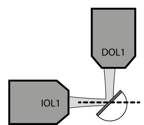
I have recently built a SPIM system based on the descSPIM open source microscope to be used for imaging cleared mouse organs (Brains and Pancreata mostly). It is essentially a compact Single Plane Illumination Microscope built entirely from parts commercially available from Thorlabs; a cylindrical lens is used for creating the light sheet. While the setup has gone well, and I have some “ok” preliminary data, I am consistently getting an axial resolution that is significantly more poor than what I believe I theoretically should achieve.

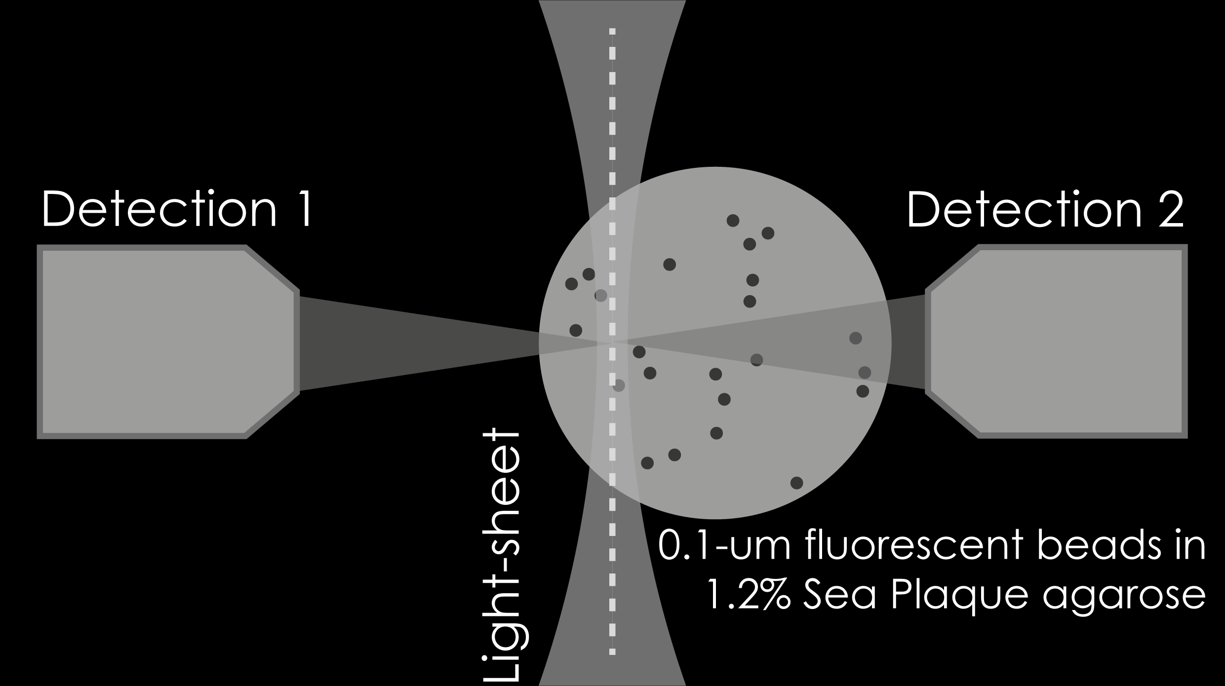
As I do not have a beam profiler, and have had trouble preparing a fluorescent bead calibration gel, I am basing my expectations on the in depth characterisation of the system in the original paper. In theory, I should be achieving a 3.45 micron lateral resolution, with the expected 3x decrease in axial resolution (~10 micron). As the first samples I imaged were prepared using (almost) the exact same protocol as the paper (CUBIC cleared nuclear stained mouse brains), I have some comparison images to illustrate my point.

The following is from the above linked paper; it is a PI stained mouse brain, which has been imaged in the dorsal-ventral plane (x-y), and shows the corresponding reoncstructed coronal section (x-z).

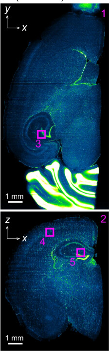
Here is from one of my prepared samples, the brain is damaged but should still illustrate the point. The only difference from this sample to the one above is I have used TO:PRO-1 instead of PI for the nuclear stain as my multi-line laser doesn’t have the wavelength capable of exciting PI.

X-Y

Imgur

X-Z (from napari)

Imgur

Thoughts so far:

My immediate first thought was that the cuvette holding my sample was undergoing some slight vibrations during the movement of the motor. However, when I imaged a nuclear stained pancreas in a PS cuvette fixed to my holder, and oversampled during imaging (i.e. moved the stage motor at a 10x slower speed to rule out miscalibration of the motor speed), I still had the same problem.

Secondly, I noticed that around certain features, for example the hippocampal region, there appears to be a sort of “doubling” or hazyness which I read in some papers can either be a result of poor clearing or an RI mismatch? As below…

[In above imgur account - image titled hippocampus doubling]

Does anyone have an intuition on which of the 2 is the more likely culprit (clearing or RI matching), and if they think this is the more probable cause of my axial resolution? If so, do you know what could be the possible cause of said problem and how I could fix it moving forward? The brain I presented was cleared for 6 days at 37 degrees in freshly made CUBIC-L so I thought the clearing should have been on the more extensive end. The RI matching was done for 2 days in freshly prepared CUBIC-R+. Here is what the agarose encased brain looked like in my cuvette:

[In above imgur account - image titled Cuvette - Optical Path]

Lastly, for preparing my agarose encased brains, I used a mould I designed and 3D printed out of PLA. As such, the mould has some very slight layer lines (printed with 0.1mm layer height) on the sides facing the direction of the excitation light path which are visible on the agarose after setting. The detection path is made using glass slides, thus have a very smooth finish. My thoughts were that as the agarose is resuspended in my RI matching medium, that the light path shouldn’t be refracted by these lines as the light first traverses through the glass → CUBIC-R+ interface. However, could this be what is causing my issues? I have tried smoothing out some of my gel moulds using Dichloro Methane, as it is very difficult to use sanding for molds that small, however I found that DCM is quite aggressive with melting PLA and in practice it is quite difficult to get a smooth finish. For what its worth, this is the view of the cuvette from the laser light path.

[In above imgur account - image titled Cuvette - Excitiation Path]

I would really appreciate some insight from people who have had more experience than me in preparing samples for SPIM microscopy, who may be able to guide me on how to troubleshoot my problems further!

@engpol

Welcome to this community.

I can’t give you an answer to your questions but I suggest you try again with the fluorescent beads. What problems did you have that you didn’t manage? An image of beads will be tremendously helpful in the way of troubleshooting.

Another thing, beam profilers are nice, but also quite pricey. Under the hood those are just cameras with beam profiling capacity in the form of a software. Too see your light-sheet, you could use any camera without its lens. You won’t be able to easily measure properties of your beams, but measuring the thickness of your light-sheet in a post-processing step shouldn’t be too difficult. If you are tight on budget, you could even get a cheap webcam and remove its lens. Otherwise, I like to use small machine vision cameras for the task, such as https://www.edmundoptics.com/p/bfs-u3-63s4m-c-usb3-blackflyreg-s-monochrome-camera/40165/, which is 494.19USD at the time of writing this answer. I am not affiliated with Edmund Optics or Teledyne.

I hope this helps and take care,

Omni

1 Like

@Omnistic

Thanks for the warm welcome and thanks so much for the helpful suggestions!

Not sure why I didn’t think of just using a webcam to measure my beam width :upside_down_face:. I’ve ordered an RPi Camera V2 for this as it has a very easily removable lens, and I can hook it up to an RPi Zero which can probably just live in my optical enclosure. I’ll see how that goes.

As per making the the fluorescent bead calibration gel; For whatever reason, I am struggling to detect a strong enough fluorescence signal from my beads to able to visualise in on my SPIM system. I bought the 1micron ThermoFisher TetraSpeck beads, which have ex/em compatible with my lasers, and should be sub-resolution of my setup (3.45 micron). However, even when visualising the beads on an epifluorescence microscopy system, the signal I can detect is really quite weak even at maximum illumination. When making the gel for SPIM, I feel like I tried most steps I saw online - sonicating the beads, not adding the beads to the agarose until it reached a sufficiently low temperature - I add at agarose which is kept in a water bath at 60o - and suspending and vortexing first in H2O.

I do seem to remember reading some sentiments online about multi-colour beads being less bright than single colour versions (not sure why, perhaps due to FRET?), so perhaps I may need to buy some new beads. Is there any companies/specific products that you recommend for making calibration gels for LSFM? The laser wavelengths I have access to are: 488, 515, 561 and 647, if that affects your anwser.

Thanks again for the help!

Olivier

@engpol

It is a good idea to use the RPi Camera V2. It seems to be based on SONY IMX219, from what I can search. I think you should be able to see your light sheet with this one.

Another thing that came to my mind is that in our light sheet (SIMVIEW, Keller Lab, Janelia) we had a custom sample consisting of a mirror that could be rotated. That way you can use the detection camera to view your light sheet profile. Though I must say it was somewhat tricky to adjust. I need to search my notes but if you are interested let me know. It looked like so (IOL: Illumination Objective Lens | DOL: Detection Objective Lens):

I was always lucky with my TetraSpeck beads and they worked quite well for me, even old batches. My main issue generally is to get the concentration (of beads) right. We were making relatively low concentration (1.2% in Milli-Q water) of SeaPlaque agarose (we were told this was the best agarose in terms of transparency and refractive index, though we never tested those claims). The sample was formed by injecting the mixture into capillaries (2-mm internal diameter). When solidified, the cylinders of agar were slightly pushed out of the capillary to not have the glass walls on the light path with dental wax. I even found some old code to process the data in case it might be helpful (I never intended to share this and it was written long ago so sorry for poor quality):

Another thing, can you clarify how you generated the X-Z cut? You have written (from napari) but its not clear how this was made. Could it be the issue? I’m not so familiar with Napari, but in Fiji/ImageJ you’d use Image..Stacks..Reslice.. to generate a X-Z and you can force without interpolation to get as raw data as possible.

Take care,

Omni

@Omnistic

Thank you again for insight on the beads and other ways of visualising my light sheet.

Putting a rotating mirror in the sample holder is really cool! My sample holder rotates on a 360o axis, so in theory this could be easy to apply to my setup. However, as I am quite limited in space in my sample holder (~22 mm x 22mm), to fit most mirrors that I could buy from Edmund Optics/Thorlabs I think I’d have to design a custom fixture/holder that is more space efficient. Maybe I’ll see how the RPi Cam serves me first…

As the descSPIM sample holder is designed to fit cuvettes (including standard 12.5mm PS), I tried 2 methods of fitting my agarose-bead sample into said cuvettes:

  1. Pouring the agarose-bead mixture directly into the cuvette and letting it set. (I only tried this a couple times, as I found the agarose would at certain points detach from the walls of the cuvette, and I was also wondering if in the time it took for the agarose to set, the beads would sink to the bottom and not be evenly distributed)

  2. Use a gel mold of a smaller size than my cuvette (this also allowed me to let the gel set in layers, with the agarose mixture being lightly vortexed at each step to resuspend the beads evenly, and hopefully stop the beads falling to the bottom), placing the agarose sample in the cuvette and filling the gaps around the gel up with my RI matching medium (for me this is CUBIC-R).

Is there a benefit to using small capillaries for setting my bead-agarose? Other than, I’m assuming, saving on the amount of fluorescent beads used and perhaps decreasing the time for the agarose to set?

Also, could you give me a rough idea of how much you would dilute your TetraSpeck beads? When looking at the beads suspended on slides in my epifluorescence system, I found that dilutions in the ranges of 1:100 - 1:1000 seemed to result in a nicely distributed FOV. However, even in agarose-bead samples towards the higher end (1:250 is the highest I tried, I believe) I couldn’t detect the beads on my SPIM.

The X-Z reslice I generated using the roll dimensions button in napari. I looked it up, and apparently by default napari uses nearest neighbour interpolation for any volume rendering (including changing order of dimensions). I just loaded in the data presented above into Fiji and used the Image..Stacks..Reslice.. approach to generate the X-Z view without interpolation, and while it may look ever so slightly better (not sure if it’s just my bias), it does look for the most part the same. So I don’t think this is the root of my problem.

Finally, thanks for the code! If I get some nice bead images I’ll be sure to give it a go!

Sincerely,

Olivier

@engpol

Indeed the mirror had to be cut to fit our narrow sample volume, but I don’t know how they did it. I see that Thorlabs has a 7-mm diameter one (PF03-03-P01). I am not affiliated with Thorlabs.

Regarding filling the cuvette with agarose, the issue is the transparency. I had made some figures to illustrate the issue in our case. EDIT: the whole cylinder is immersed in water (not drawn) to minimize RI mismatch and we used water-dipping objective lenses.

These are the corresponding images from the two cameras.

The contrast was adjusted, but you already see how noisy the image gets on the second camera (one on the right-hand side, Detection 2) where the fluorescence light has to travel through more thickness of agarose. Compare it to the image on Detection 1 (left-hand side). Bear in mind this was a 2-mm diameter cylinder. Since your cuvette has a square section you’ll have attenuation of your light sheet as it come to a focus, and you’ll have attenuation of the fluorescence towards your camera. You can minimize the latter by moving the light sheet close to the cuvette wall that is closer to the camera.

The dilution in my notes is 5uL of beads in 1mL of 1.2% agarose (SeaPlaque) but I remember I didn’t have access to a ultrasonic bath so it might not be representative. From my experience, around 1:100 is quite dense but I like it because it is easier to see and still I was able to process the data (not too much overlap).

Let me know if this helps and good luck troubleshooting.

Take care,

Omni

1 Like