Dear μforum community,
I would like to add a 1W laser around 647nm in order to do single protein imaging. Specifically, I have a Nikon Ti2-E inverted widefield microscope, and want to achieve Kohler-based widefield illumination with 10-30 kW/cm^2 power density, over an exposure time of 500 microseconds, in order to image a free mobile protein, and I would like the illumination field, when using a 100x objective, to be around 40um^2. I specifically want widefield, and not TIRF.
Currently, I am considering a free running Fabry Perot 647nm, 1W laser diode. My concept, based on some literature, is to take this spectrally diverse laser source - since it has many longitudinal modes spanning over 2nm FWHM, and to combine it with a step index multimode fiber, that’s several meters long, 100um diameter, and NA 0.22. The many longitudinal modes, that are seperated by more than around 0.01nm would have independent speckle patterns, which when averaged by the Halotag dye, which doesn’t distinguish much between +/- 1nm, would be effectively homogenous excitation of the dyes in the illumination field.
My understanding is that this setup can PASSIVELY result in a homogenous illumination field at the sample plane, even without a vibrator. Specifically, because I am taking a 500 us exposure, I can’t completely rely on a 10 kHz vibrator to provide enough speckle patterns to average out the speckles.
I would love to hear recommendations from the community, regarding what is good with this idea, and potential problems or considerations.
Please see the figures below that I’ve copied from open access papers, which I think show some indication regarding this design for passive reduction of specklie, ie, achieve a uniformly illuminated sample plane.
Thank you for your time.
Warmly,
Yossi
Schröder D, Deschamps J, Dasgupta A, Matti U, Ries J. Cost-efficient open source laser engine for microscopy. Biomed Opt Express. 2020 Jan 3;11(2):609-623. doi: 10.1364/BOE.380815.

Fig. 7. Speckle-reduction at different exposure times. (a) Central area of the square multimode fiber at different exposure times for each laser line. The leftmost column is the profile at 5 ms exposure time without agitation. The other columns are the agitated profiles at the exposure time indicated on top of each column. (b) The speckle contrast with agitation (solid line) for the 405 nm laser diode plotted against the exposure time and compared with the speckle contrast in the absence of agitation (dashed line). The output power was 50 mW. (c) Same for the 488 nm laser diode, with 30 mW laser power. (d) Same for the 561 nm dpss laser, with 200 mW laser power. (e) Same for one 638 nm laser diode, with above 400 mW of laser power.
Kwakwa K, Savell A, Davies T, Munro I, Parrinello S, Purbhoo MA, Dunsby C, Neil MA, French PM. easySTORM: a robust, lower-cost approach to localisation and TIRF microscopy. J Biophotonics. 2016 Sep;9(9):948-57. doi: 10.1002/jbio.201500324.

Supplementary figure 3Excitation intensity images and line sections across diameter of field of view for TIRF microscopy illumination with 638 nm laser radiation from multi-mode diode laser using (a) static delivery optical fibre and (b) optical fibre with vibrating despeckler unit.
Almahayni K, Nestola G, Spiekermann M, Möckl L. Simple, Economic, and Robust Rail-Based Setup for Super-Resolution Localization Microscopy. J Phys Chem A. 2023 May 25;127(20):4553-4560. doi: 10.1021/acs.jpca.3c01351.
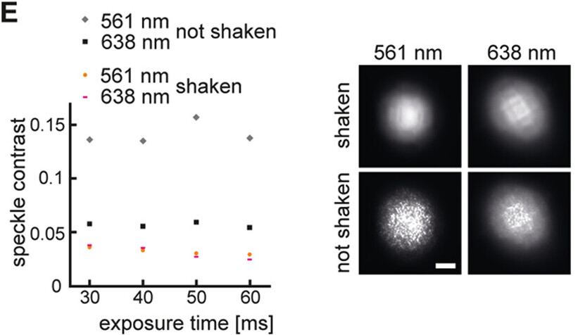
Figure 1. Setup design and characterization. (A) Setup design. Shaded areas indicate parts installed on rails. (B) Photographs of the setup (i) side view, (ii) top view. (C) Beam profiles for the 561 and 638 nm lasers. Black: Recorded profile, red: Gaussian fit. (D) Camera pixels before and after correction, chosen deviation threshold is indicated in red as 3%. (E) Reduction in speckle contrast with and without shaking the fiber for both excitation options. Scale bars: 3 μm (D), 20 μm (E).
Also see plausibly relevant figure in the following papers.
Figure 4 in Zhou, J., Le, Z., Guo, Y., Liu, Z., Xu, Q., Dai, Y., Deng, J., Li, J., & Cai, D. (2021). Investigation on Speckle-Free Imaging at the Output of a Multimode Fiber under Various Mode Excitation Conditions. Photonics, 8(5), 171. https://doi.org/10.3390/photonics8050171
Figure 1 in Redding B, Cao H. Using a multimode fiber as a high-resolution, low-loss spectrometer. Opt Lett. 2012 Aug 15;37(16):3384-6. doi: 10.1364/OL.37.003384.
Table 1 in Manni JG, Goodman JW. Versatile method for achieving 1% speckle contrast in large-venue laser projection displays using a stationary multimode optical fiber. Opt Express. 2012 May 7;20(10):11288-315. doi: 10.1364/OE.20.011288.
Figure 1 in Open Blink: Low-cost TIRF microscopy for super-resolution imaging via µManager
Ran Huo, Jelle Komen, Moritz Engelhardt, Anaïs Millot, Jérôme Extermann, Kristin Grußmayer
bioRxiv 2026.03.10.710894; doi: Open Blink: Low-cost TIRF microscopy for super-resolution imaging via µManager | bioRxiv